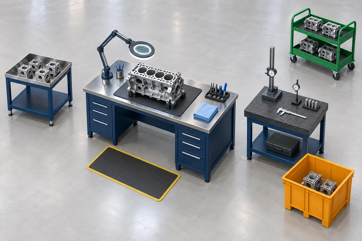
Explore 34 checks using visual inspection, manual measurement and gauges on four interactive components. See the defect, understand the instrument and record the finding. Or sketch your own inspection flow. Staffing calculations are optional.
Bore gauging, caliper dimensions, deck gap and height checks, finish comparison and threads.
View controls
Scroll to move the page · drag to rotate · pinch or + / − to zoom · Home resets the view
LOADING 3D
Preparing engine block…Loading the interactive model.
ILLUSTRATIVE GEOMETRY · not to scale
V1 · Example resultReady to inspect
EB-04 / VA-01 · DEMO Rev A
Sealing-face surface discontinuities
Machined deck · localised pitting
These small holes interrupt a surface that needs to seal against another component. Select the point to look closer.
Example acceptance criterionTeaching example: no open pits in this marked sealing area.
Instrument / method
Inspection light + magnifier
Set-up & reference
Clean surface; controlled viewing angle and illumination
Coverage
Specified sealing region; full accessible coverage
Functional relevance
A pit in a critical sealing area may create a leak path. Location and the drawing requirements determine acceptability.
0 / 10 on this part0 saved in session · 0 requiring review
Educational model · fictional drawing and readings, enlarged defects and schematic tools. This is an inspection example, not production CAD or a release record. Display resolution is not measurement accuracy.
Go deeper
From one check to a complete inspection plan.
Open a guide to explore the terminology, process and layouts behind a controlled final inspection.
01
Technical parameters & reporting
CTQ, fixture references, MSA, uncertainty and inspection records.
+
02 / From drawing to decision
The parameters behind a reliable result.
Inspection is more than a pass or fail. Explore the controls that make the result meaningful for your engineering and quality teams.
01 / DRAWING CONTROL
CTQ characteristics
Critical-to-quality features connect a drawing requirement to component function. Identify each characteristic, its revision and acceptance criterion before inspection.
Agree: characteristic numbers, severity and customer requirements.02 / REFERENCE SYSTEM
Supports & reference faces
Use the drawing-defined reference faces and an approved support or fixture. The contact position and support arrangement must be repeatable before comparing readings or applying a gauge.
Agree: reference faces, support points and fixture setup.03 / COVERAGE
Sampling & containment
A sampling plan and 100% sorting answer different needs. Set the lot definition, sample size, acceptance criteria and escalation route for the actual risk.
Agree: lot size, sampling basis, suspect stock and re-inspection scope.04 / METHOD
Measurement strategy
Bore diameter at one point cannot establish the condition of the whole bore. Define axial sections, measuring directions, instrument contacts and accessible surfaces.
Agree: inspection locations, measurement sequence and coverage limitations.05 / ENVIRONMENT
Part preparation
Cleanliness, temperature, burrs and clamping can affect results. Stabilise and prepare the part and measurement setup before recording values.
Agree: handling, cleaning, environment and fixture requirements.06 / ACCEPTANCE
Decision rules
A reading near a limit needs the agreed acceptance rule and consideration of measurement uncertainty. Record the actual value as well as the disposition.
Agree: tolerance, uncertainty treatment and concession authority.
Identity, preparation, checks, evidence, segregation and authorised release.
+
03 / Follow the process
Final inspection, step by step.
Link each finding to a requirement, record the result and make the part’s status clear.
Step 1 of 6
Start with the right part and requirement.
Confirm what is being inspected and which drawing, revision and inspection plan apply. A precise measurement against the wrong requirement is still the wrong decision.
Part or lot identity
Current approved drawing
Defined checks and acceptance criteria
Engine-block teaching example
EB–04Final inspection
Right part. Right revision.Part identity + approved requirements
At this stepA known part, a known requirement and a clear scope.
A passed size check does not cancel a visual defect.
03
Inspection stages, methods & coverage
Incoming vs final, visual vs dimensional, sampling vs every-piece checks.
+
04 / Know the difference
When do we inspect? How do we check?
Inspection stages, methods and coverage describe different parts of the plan. Select each to see how they fit together.
A
The stage tells us when.
After the planned work, before release
Does the finished part meet the agreed requirements?
Bring the required appearance, dimensional, identity and record checks together before the part is released to the next operation or customer.
On an engine block
inspect the finished surfaces, check specified dimensions, review records and confirm the part status.
What might be checked
Finished-part visual and dimensional checks
Completion of required tests and records
Identification, protection and release status
What comes out of it
A final inspection record with an authorised disposition.
B
The method tells us how.
A final inspection may combine several methods. Select one to see what it can tell you.
What can we see?
Look for specified surface damage, burrs, contamination, missing features and identification errors. Follow the agreed viewing conditions and accessible-surface coverage.
Typical tools or evidence
Inspection light, magnifier, mirror and approved defect samples.
On this engine block: pits on the deck, a burr on the casting and scoring inside an accessible bore.
A good appearance does not confirm dimensions or the condition of hidden surfaces.
C
The coverage tells us how many.
Checking every piece and inspecting a defined sample are different approaches.
010203040506070809101112131415161718192021222324
Selected for the checkOutside this sample
100% inspection
Every unit receives the specified check. This does not mean every possible characteristic is checked, or that errors are impossible.
The inspection plan still defines the feature, method, acceptance rule and record.
Explore a bench, sorting line and U-shaped cell with controlled part flow.
+
05 / Explore the layout
A good layout makes part status easy to see.
Select a layout, then a numbered point on the image. Follow the part from input to inspection, records and controlled output.
Interactive teaching illustration · not a photograph of a Pioneer facility. Layouts are conceptual, not scaled floor plans.
The principle stays the same: make the input, inspection, records, accepted output and hold route clear. Adapt the actual setup to the part, workflow and agreed inspection plan.
Layout Studio
Explore the flow. Develop your idea.
Start with a ready flow. Add blocks, draw routes and compare ideas. Calculations are optional: choose Plan the team whenever you want to estimate staffing.
LAYOUT STUDIOConnecting rod
Start with a flow that feels familiar.
Connections are ready. Change anything; Undo brings your previous plan back.
Drag a card · Connect the dots · Try an idea
Sketch it. Try it. Keep the better idea.
Add steps and drag the blue dots for part flow, amber for defects. Save alternatives in Saved ideas. Switch to Plan the team whenever you want numbers.
Drag blocks, connect routes and play the flow. Timings are optional.
Choose a starting flow, add blocks and connect your idea. Team calculations are optional.
Planning estimates are for discussion, not a quotation or a production guarantee. Confirm times, space, tools and acceptance criteria with a site review. Example values and floor positions are illustrative. Customer equipment blocks do not describe Pioneer’s owned equipment or service scope.
Put an inspection plan around your part.
Share the component, drawing revision, quantity and location. Pioneer can review the visual criteria, measurement scope, containment route and reporting requirements with your team.
Use the Studio to understand the checks before discussing a real assignment. Start with one component and one characteristic; the instrument, example result and next action sit beside the model.
01
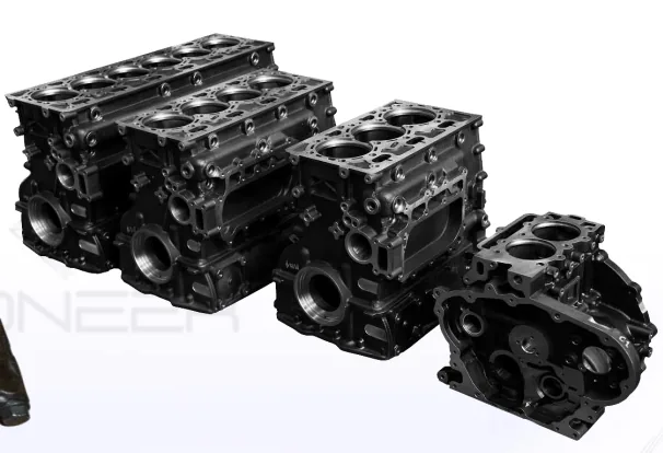
Engine block
Visible pitting and burrs, bore-gauge readings, caliper dimensions, deck gaps and thread acceptance.
02
Connecting rod
Forging flash, bore scoring, bore-gauge readings, end width, plug-gauge acceptance and local gaps.
Enclosure condition, caliper dimensions, locating-pin fit and flange gaps on a passive assembly.
Teaching models and example readings are illustrative. The EV example covers a passive enclosure; it does not demonstrate electrical or high-voltage testing.
Choose a component, select a characteristic and press Inspect. Read the method and example result, then save the result from Report. You can export the recorded checks as CSV or Excel; the Excel report includes a Pareto chart.
Do I need cycle times or staffing numbers?
No. Layout Studio starts with an untimed flow for brainstorming. Move stations, add blocks and connect routes. Choose Plan the team only when you want an estimate based on your quantities, available time and station inputs.
Can this example approve a production part?
No. The models, readings and reports are demonstrations. A real inspection uses the agreed drawing revision, acceptance criteria, suitable instruments and authorised disposition. Read the final inspection checklist and guide to inspection reports.
Can Pioneer inspect parts in India for an overseas buyer?

 Preparing engine block…